Introduction
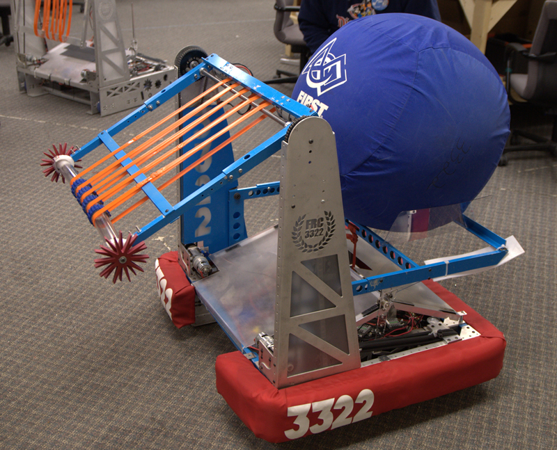
I’ve been a part of FIRST Robotics Team 3322 for some time now, and every year it seems I learn new things about how FIRST Robotics drivetrains should be designed. This is a guide for beginner and intermediate designers to learn a little about better drivetrain design.
What will be covered:
- CIM Motor Basics
- Gearing
- Wheel Sizes
- Thrust
- Design Guidelines
So if you are ready, let’s jump right in.
The CIM Motor
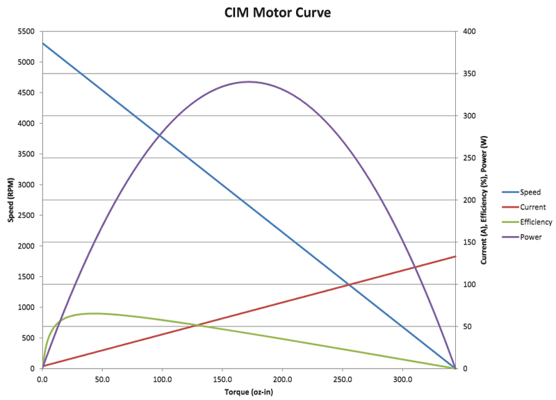
We are going to start in by taking a careful look at a CIM motor, as almost all FIRST drivetrains are powered with 2,4, or 6 CIM motors. There are many layers to the complex issue of deciding what a motor will provide for any design, but we mostly want to answer the following question: What speed and torque can we count on? Keep in mind that on a FIRST robot there are 40A breakers behind each CIM motor.
If we examine the motor curve for a CIM we find that we can count on 100oz-in of torque from a CIM motor at 40A and free speeds above 5000rpm. Note that in practice, 40A breakers are heat-driven, and will allow current much greater than 40A for brief instances. Also be aware that it is unlikely that you are getting 12V from your 12V battery.
We are going to assume a 4500rpm free speed (which is a high assumption), and 100oz-in torque (which is low). In better units, this is 75rps (rotations per second) and 6.25lb-in of torque
Gearing
For our purposes, gearing is any method to trade speed for torque or vice-versa (or speed for output thrust). If you don’t understand the basic principles of using different gear ratios to alter torques and speeds, read up on it right now. Most drivetrains start with a gearbox that gears the CIM motors down between 4:1 and 12:1.
Let’s have a look at how that works for the 2014 Kit of Parts drive system. I’m pretty sure the drive system uses a 8.45:1 gear ratio. This means that the motor spins 8.45 times to spin the output shaft of the gearbox once. Whenever you are gearing down, you can multiply the torque by the gear ratio, and divide the speed by the gear ratio. Note that there are actually some losses in gearing (which grease and good bearings help alleviate). While we calculate 52.8lb-in of torque, it is more likely that we are getting 50lb-in of torque.
6.25lb-in of torque x 8.45 = 52.8lb-in of torque

75 rotations/second /8.45 = 8.88 rotations/second
Note that sprocket ratios will also act as a form of gearing. If you were using a 16 tooth sprocket on the output shaft of your gearbox, and a 32 tooth sprocket on your wheels, you are getting a 32:16 or 2:1 gear ratio.
Choosing your Wheel Size
Like choosing a motor, choosing the right wheel size for your application can be complicated. To keep it simple, we want to answer the following questions: What speed will the wheels yield?How heavy are the wheels? Do the wheels geometrically fit in our design space?
Let’s have a look at the first question. How does wheel size effect robot speed? In the above example, our wheels move at 8.88 rotations per second.
4″ wheel -> circumference = pi*D = 4in*3.14 = 12.6in = 1.05ft
In other words, one rotation of a 4″ wheel equals 1.05ft of travel. Lets convert our 8.88rps to linear speed. A 4″ wheel connected at a 1:1 ratio (or directly on) our example gearbox will have the following speed:
4" wheel -> 1.05 ft/rotation * 8.88 rotations/second = 9.32 ft/second

6" wheel -> 1.57 ft/rotation * 8.88 rotations/second = 13.9ft/second
You can clearly see that larger wheels get us faster speeds at a proportional rate. What’s the downside? You lose thrust.
What is Thrust?
Thrust is the amount of forward force that can accelerate our robot. In our above example, we have one CIM motor producing 6.25lb-in of torque through a 8.45:1 gearbox. That totals 52.8lb-in of torque. Let’s connect a couple wheel sizes to that and see what happens.
Remember that torque = force * radius to center of rotation

4" wheel -> force of thrust (Ft) = torque/radius = 52.8lb-in/2in = 26.4lb thrust

6" wheel -> Ft = 52.8lb-in/3in = 17.6lb thrust
A pair of CIM motors at our 8.45:1 drivetrain with 4″ wheels produces 52.8 lb of thrust (26.4lb per CIM). Lets put that in real terms – a 100lb robot will push with a maximum of 52.8lb of force and accelerate at roughly .5g, or 16ft/sec/sec. A 150lb robot will also push with a maximum of 52.8 lb of force, but accelerate at roughly .33g, or 11ft/sec/sec.
Designing for Balance
It should be fairly clear by now that you can use different wheel sizes, gearboxes and chain/belt sprockets to create a gearing that balances top speed versus thrust to accelerate or push other robots. Make a list of gearboxes, wheel sizes and sprocket ratios available to you. Use various combinations of these parts to get the right balance of speed and thrust for your design.
The Kit of Parts drivetrain is well designed and well balanced. With 4 CIM motors, it should produce about 100lb of thrust with a top speed around 9fps.
Shifting Gearboxes
Shifting gearboxes are awesome. Use a KOP drivetrain and slap shifting gearboxes on them to seriously upgrade your robot.
Shifting gearboxes allow teams to design for two separate gear ratios: One aimed at high thrust and one aimed at high speed – getting the best of both worlds. Typically, good teams will design a low gear that produces so much thrust that their wheel friction limits their pushing ability, and a high gear that targets a speed between 12-16fps (or sometimes higher).
Stay tuned and I will try to post some material on friction, wheel choices, and other drivetrain design topics.